%20--%3e%3cpath%20d='M2025.4,806.8c-2.5,20.1-16.2,38.2-34.5,45.1-3.4,1.3-8.4,2.3-14.6,3.2-14.2,1.9-34.3,2.8-53.7,2.7h-.2c-23.1-.1-45.1-1.7-54.4-4.4-2.5-.7-4.9-1.6-7.2-2.7-.2,0-.3-.2-.5-.2-8.2-3.8-15.6-9.8-21.1-17.1-5.7-7.6-9.4-16.8-10-27,0,0,0,0,0,0-.5-3.1-.8-6.3-1.1-9.7-.5-7.2-.9-16.4-1-26.5h281.9c0-63.9-2.2-130.2-61.1-167.8-37.4-23.8-95.6-24.8-152.9-22.2-52.8,2.3-90.5,17.6-115.3,46.6-24.2,28.3-35.5,68.9-34.5,125.8h0c.2,12.6,1,26,2.4,40.2.3,3.1.6,6.2,1,9.4,2.9,25.9,12.9,50.3,28.9,70.4,10.9,13.8,24,24.9,38.8,32.8,7.6,4.1,15.7,7.4,24.1,9.8,17.8,5,52.5,7.8,87.8,7.8s64.2-2.2,84.5-7.1c2.9-.7,5.5-1.4,7.8-2.2,45-15,82.5-60.5,85.6-106.7h-80.6ZM2025.3,709.9h-198.3v-2.6c0-33.2,26.7-58.2,64.8-58.2h72.8c30.3,0,60.8,24.9,60.8,58.2v2.6Z'/%3e%3cpath%20d='M1620.8,806.8c-2.5,20.1-16.2,38.2-34.5,45.1-3.4,1.3-8.4,2.3-14.6,3.2-14.2,1.9-34.3,2.8-53.7,2.7h-.2c-23.1-.1-45.1-1.7-54.4-4.4-2.5-.7-4.9-1.6-7.2-2.7-.2,0-.3-.2-.5-.2-8.2-3.8-15.6-9.8-21.1-17.1-5.7-7.6-9.4-16.8-10-27,0,0,0,0,0,0-.5-3.1-.8-6.3-1.1-9.7-.5-7.2-.9-16.4-1-26.5h281.9c0-63.9-2.2-130.2-61.1-167.8-37.4-23.8-95.6-24.8-152.9-22.2-52.8,2.3-90.5,17.6-115.3,46.6-24.2,28.3-35.5,68.9-34.5,125.8h0c.2,12.6,1,26,2.4,40.2.3,3.1.6,6.2,1,9.4,2.9,25.9,12.9,50.3,28.9,70.4,10.9,13.8,24,24.9,38.8,32.8,7.6,4.1,15.7,7.4,24.1,9.8,17.8,5,52.5,7.8,87.8,7.8s64.2-2.2,84.5-7.1c2.9-.7,5.5-1.4,7.8-2.2,45-15,82.5-60.5,85.6-106.7h-80.6ZM1620.8,709.9h-198.3v-2.6c0-33.2,26.7-58.2,64.8-58.2h72.8c30.3,0,60.8,24.9,60.8,58.2v2.6Z'/%3e%3cpath%20d='M2968.1,806.8c-2.5,20.1-16.2,38.2-34.5,45.1-3.4,1.3-8.4,2.3-14.6,3.2-14.2,1.9-34.3,2.8-53.7,2.7h-.2c-23.1-.1-45.1-1.7-54.4-4.4-2.5-.7-4.9-1.6-7.2-2.7-.2,0-.3-.2-.5-.2-8.2-3.8-15.6-9.8-21.1-17.1-5.7-7.6-9.4-16.8-10-27,0,0,0,0,0,0-.5-3.1-.8-6.3-1.1-9.7-.5-7.2-.9-16.4-1-26.5h281.9c0-63.9-2.2-130.2-61.1-167.8-37.4-23.8-95.6-24.8-152.9-22.2-52.8,2.3-90.5,17.6-115.3,46.6-24.2,28.3-35.5,68.9-34.5,125.8h0c.2,12.6,1,26,2.4,40.2.3,3.1.6,6.2,1,9.4,2.9,25.9,12.9,50.3,28.9,70.4,10.9,13.8,24,24.9,38.8,32.8,7.6,4.1,15.7,7.4,24.1,9.8,17.8,5,52.5,7.8,87.8,7.8s64.2-2.2,84.5-7.1c2.9-.7,5.5-1.4,7.8-2.2,45-15,82.5-60.5,85.6-106.7h-80.6ZM2968,709.9h-198.3v-2.6c0-33.2,26.7-58.2,64.8-58.2h72.8c30.3,0,60.8,24.9,60.8,58.2v2.6Z'/%3e%3cpath%20d='M2402,586.8c-33.3-9.5-98.1-9.6-133.7-3.3-28.1,4.9-55.3,19.7-76.7,41.5-21.4,21.8-35.7,49.3-40.3,77.5-10.8,65.9,0,123.9,30.3,163.2,24.8,32.1,61.3,50.7,108.4,55.2,14.2,1.3,27.5,2,40.1,2,30.6,0,56.9-4,79.6-12,39.8-14,69.4-40,86-79.2,8.9-20.9,11.3-36.7,11.3-59.5v-1h-78.2s1.1,63.5-43.7,75.9c-26.4,6.3-75.2,4-98.6,2.3-17.8-1.3-31.6-7.1-41-17.3-9-9.8-14.2-24-15.4-42.1-1.9-28.8-2.6-90.3,7.3-109.2,7.1-13.5,21.4-23.8,37.3-27,23-4.5,98.1-4.2,117.7,3.4,37.1,14.4,36.3,55.9,36.3,55.9h78.2v-2c0-26.6-10.5-55.1-31.4-78.7-19.5-21.9-47-37.8-73.7-45.4Z'/%3e%3crect%20x='2557.8'%20y='492.7'%20width='80.1'%20height='422.1'/%3e%3cpolygon%20points='1119.3%20831.5%201007.4%20585.6%20913.1%20585.6%201065%20913.6%201065.5%20914.8%201173%20914.8%201325.4%20585.6%201231.2%20585.6%201119.3%20831.5'/%3e%3cpolygon%20points='265%20601.6%20265%20810.4%20627.6%201019.1%20627.6%201019.1%20627.6%201019.1%20627.6%201019.1%20627.6%201019.1%20808.9%20914.8%20808.9%20706%20627.6%20810.4%20265%20601.6'/%3e%3cpolygon%20points='808.9%20706%20808.9%20497.2%20627.6%20601.5%20808.9%20706'/%3e%3c/svg%3e)
From datasheet to running firmware in one prompt
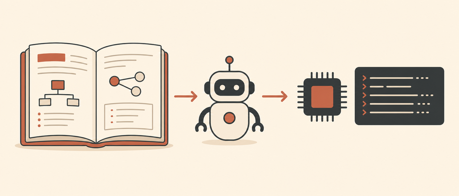
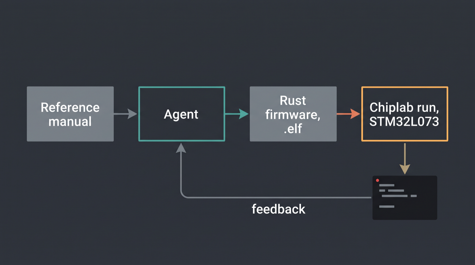
An AI agent can bring up firmware on an unfamiliar board from the reference manual alone, on the first attempt, if it can run what it writes. Here is the run that shows it, including the part that didn't work.
Almost every demo on this blog uses an STM32F4. That's not an accident, it's a habit. The F4 is the part I know best, it's the part with the most sample code on the internet, and any model you'd care to use has seen a thousand blinky examples for it. Asking an agent to write firmware for an F4 is barely a test. It's recall.
So I gave it something else: a NUCLEO-L073RZ. Cortex-M0+, low-power L0 family, a different clock tree and a different peripheral map from anything else in this series. One prompt, no starter project, no working example to copy from. Read the manual, write the firmware, run it, show me UART output.
Why this board is a real test and the F4 isn't
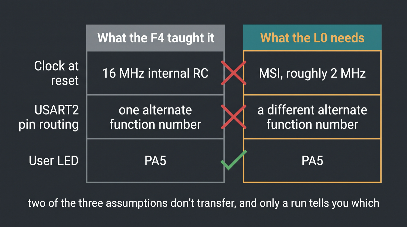
Three things have to be right before a single character shows up on a serial line, and on the L0 all three are different from the part the agent has the most training data for.
The clock. An F4 comes out of reset running on its 16 MHz internal RC oscillator. An L0 does not, it comes up on MSI, the multi-speed internal oscillator, at roughly 2 MHz. If you write F4 habits into L0 code you get a chip that runs, and a baud rate that's wrong by a factor of eight, which means a UART that prints garbage rather than nothing. Garbage is worse. Nothing tells you the peripheral never came up. Garbage tells you it did, and then you spend an hour looking at the wrong layer.
The pins. USART2 is on PA2 and PA3, which happens to match the F4. What doesn't match is the alternate-function number that routes the pin to the peripheral. Every family reshuffles that table, and the reshuffling is the entire content of a datasheet's pin-assignment section. Pick the F4 number on an L0 and the GPIO is configured, the USART is configured, and the two are not connected to each other.
The LED. PA5, LD2 on a Nucleo-64. This one is genuinely the same, and it's the only free lunch in the list.
None of this is hard. It's just specific, and "specific" is exactly where a model with no way to check its work falls apart. Every chip is an island, and the bridge is the manual.
The firmware it wrote
Rust, no_std, stm32l0xx-hal. This is the code that ran, not a cleaned-up version of it:
#![no_main]
#![no_std]

use cortex_m_rt::entry;
use embedded_time::rate::Extensions;
use nb::block;
use panic_halt as _;
use stm32l0xx_hal::{pac, prelude::*, rcc::Config, serial};

const DBGMCU_IDCODE: *const u32 = 0xE004_2000 as *const u32;

#[entry]
fn main() -> ! {
    let dp = pac::Peripherals::take().unwrap();
    let mut rcc = dp.RCC.freeze(Config::hsi16());
    let gpioa = dp.GPIOA.split(&mut rcc);

    let serial = dp.USART2.usart(
        gpioa.pa2, gpioa.pa3,
        serial::Config::default().baudrate(115_200_u32.Bd()),
        &mut rcc,
    ).unwrap();
    let (mut tx, _) = serial.split();
    let mut led = gpioa.pa5.into_push_pull_output();

    // ... prints a banner, reads DBGMCU_IDCODE, toggles PA5 six times over UART ...
}
The interesting line is the third one in main. Config::hsi16() switches the clock tree off
MSI and onto the 16 MHz internal oscillator, and hands the resulting frequency to rcc, which
is then passed into the USART constructor so the baud divider is computed against the clock that
is actually running. That's the whole trick, and getting it wrong is the single most common way
to end up with a serial port that prints noise.
The pin routing never appears in the source because the HAL owns it. dp.USART2.usart(gpioa.pa2, gpioa.pa3, ...) only compiles for pins that can physically carry that peripheral on this
family, and the crate sets the alternate function itself. That's not the agent being clever,
that's the Rust embedded ecosystem having encoded the datasheet into the type system a decade
ago. The agent's job was to know that the crate works this way and reach for the right two
pins. It did.
The run
Board stm32l073_nucleo. Unedited stdout:
08:07:06.8801 [WARNING] usart2: Unhandled write to offset 0x8. Unhandled bits: [13] when writing value 0x20C0. Tags: DDRE (0x1).
08:07:06.8859 [INFO] usart2: [host: 0.19s (+0.19s)|virt: 0.51µs (+0.51µs)] datasheet-agent: never seen this board before, reading DBGMCU_IDCODE
08:07:06.8880 [WARNING] sysbus: [cpu: 0x8000290] ReadDoubleWord from non existing peripheral at 0xE0042000.
08:07:06.8885 [INFO] usart2: [host: 0.19s (+2.75ms)|virt:     0.51µs (+0s)] DBGMCU_IDCODE = 0x00000000
08:07:06.8896 [INFO] usart2: [host: 0.19s (+1.12ms)|virt:     0.51µs (+0s)] toggle 0 -> PA5 on
08:07:06.8899 [INFO] usart2: [host: 0.19s (+0.32ms)|virt:     0.51µs (+0s)] toggle 1 -> PA5 off
08:07:06.8901 [INFO] usart2: [host: 0.19s (+0.25ms)|virt:     0.51µs (+0s)] toggle 2 -> PA5 on
08:07:06.8904 [INFO] usart2: [host: 0.19s (+0.25ms)|virt:     0.51µs (+0s)] toggle 3 -> PA5 off
08:07:06.8906 [INFO] usart2: [host: 0.19s (+0.26ms)|virt:     0.51µs (+0s)] toggle 4 -> PA5 on
08:07:06.8909 [INFO] usart2: [host: 0.19s (+0.25ms)|virt:     0.51µs (+0s)] toggle 5 -> PA5 off
08:07:06.8916 [INFO] usart2: [host: 0.19s (+0.73ms)|virt:     0.51µs (+0s)] done, clock tree + USART2 + PA5 LED brought up on first try
Clock tree, serial port, GPIO. First attempt, no HardFault, no silent hang, readable text at the right baud rate. That last line is the agent's own print, not mine, and it's a little pleased with itself.
The timestamps are worth a second look. The whole sequence covers 0.51 microseconds of virtual time and about 190 milliseconds of host time. The gaps between toggles are host-side scheduling, not chip behavior. Simulation time and wall-clock time are different units, and if you ever write a test that asserts on the second one you'll get a flaky suite and no idea why.
The two things the log caught
This is the part I'd cut if I were selling you something.
The ID register read zero, and that's a simulation artifact
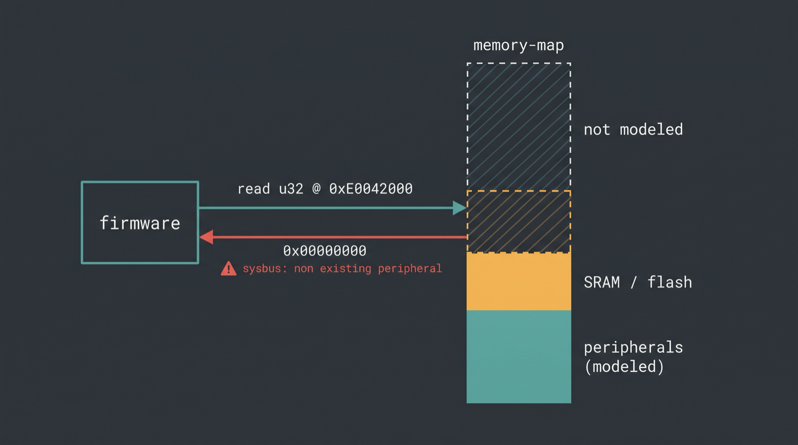
The firmware reads 0xE0042000, labeled DBGMCU_IDCODE. On real silicon the DBGMCU block holds
the device and revision ID, and reading it is the standard way for firmware to ask "what chip am
I actually on?" 0xE0042000 is the address I'm used to typing on F-series parts, which is
almost certainly why the agent typed it too.
On this virtual L0, nothing is mapped there. Renode says so in the log, in the line right before the print:
08:07:06.8880 [WARNING] sysbus: [cpu: 0x8000290] ReadDoubleWord from non existing peripheral at 0xE0042000.
The load returned 0x00000000 and execution continued. So the value in the transcript is not a
device ID. It's not a wrong device ID either. It's the absence of a peripheral, printed as a
number, and I want that stated plainly because DBGMCU_IDCODE = 0x00000000 looks exactly like a
successful read of a chip that has nothing to say.
This is the same failure mode as what simulation can't
catch, which is a whole post about our stack handing back
zeros for things that don't exist on the virtual board. That post covers why it happens and what
class of bug it hides. Here it just happened again, in a run I wasn't looking for it in, and the
only reason I noticed is that the sysbus warning was two lines above the print.
Note what did and didn't save me. The agent did not get a fault. The firmware did not misbehave. Nothing in the program's own output was wrong. The warning in the host log was the entire signal. On a physical board that read might return a real ID, or fault, or return whatever the bus leaves floating, and the point is that "the register I read is actually implemented" is an assumption you have to check on every target, in simulation or out of it.
The USART config bit the model shrugged at
First line of the run:
08:07:06.8801 [WARNING] usart2: Unhandled write to offset 0x8. Unhandled bits: [13] when writing value 0x20C0. Tags: DDRE (0x1).
Offset 0x8 is the USART's third control register, and Renode has named the bit for us: DDRE, a
DMA-related error-handling flag. The HAL set it, the model doesn't implement it, the write was
accepted anyway. It changed nothing here because this firmware doesn't touch DMA, it blocks on
the transmit register and prints. Filing it as noted-and-harmless, which is the right call for
this run and the wrong call for a run that does use DMA on receive errors.
I'm mentioning it because it's the second instance in eleven log lines of a peripheral model being less complete than the silicon, and because that pattern is not a Chiplab quirk. It's what every simulator does. The difference between simulators worth using and simulators that waste your week is whether they tell you.
What this actually proves
Not that the agent is smart. That the loop is closed.
Give the same model the same prompt with no way to run the result and you get plausible L0 code. It'll import the right crate. It might even get the pins right. But nobody, including the model, will know whether the clock configuration matched the baud divider until something prints, and "something prints" is a hardware event. Without a target, the agent's confidence and the firmware's correctness are unrelated variables.
With a target, the run is the arbiter. The firmware either brings up the clock tree or it doesn't. The UART either produces readable text at 115200 or it produces noise. The failure mode of a wrong alternate-function number is silence, and silence is an observable. That's the whole argument for putting hardware behind an API instead of behind a bench: not that simulation is better than silicon, but that an agent can call it a hundred times in an afternoon and read the result each time. The agent infrastructure map has the longer version of that argument, with the other categories that already solved it.
The unfamiliar-board part is the bit I care about most. The economics of firmware are dominated by the fact that every new part is a fresh start. New reference manual, new clock tree, new peripheral map, new HAL, and weeks of an experienced engineer's time before the first line of product code gets written. If an agent can compress the bring-up phase of a part it has never seen into one prompt and one run, that changes what "supporting a new chip" costs. The code takes minutes. Proving it takes months, and this run is a small piece of evidence that the proving part is what's actually being automated here.
One prompt, one board it had never touched, one run, clock plus UART plus GPIO on the first attempt, and one honest reminder to check whether the register you're reading exists at all. I'll take that trade.
If you want to see which other tools can close this loop and which ones only claim to, I went through every hardware MCP server I could find and wrote down what each one does.