%20--%3e%3cpath%20d='M2025.4,806.8c-2.5,20.1-16.2,38.2-34.5,45.1-3.4,1.3-8.4,2.3-14.6,3.2-14.2,1.9-34.3,2.8-53.7,2.7h-.2c-23.1-.1-45.1-1.7-54.4-4.4-2.5-.7-4.9-1.6-7.2-2.7-.2,0-.3-.2-.5-.2-8.2-3.8-15.6-9.8-21.1-17.1-5.7-7.6-9.4-16.8-10-27,0,0,0,0,0,0-.5-3.1-.8-6.3-1.1-9.7-.5-7.2-.9-16.4-1-26.5h281.9c0-63.9-2.2-130.2-61.1-167.8-37.4-23.8-95.6-24.8-152.9-22.2-52.8,2.3-90.5,17.6-115.3,46.6-24.2,28.3-35.5,68.9-34.5,125.8h0c.2,12.6,1,26,2.4,40.2.3,3.1.6,6.2,1,9.4,2.9,25.9,12.9,50.3,28.9,70.4,10.9,13.8,24,24.9,38.8,32.8,7.6,4.1,15.7,7.4,24.1,9.8,17.8,5,52.5,7.8,87.8,7.8s64.2-2.2,84.5-7.1c2.9-.7,5.5-1.4,7.8-2.2,45-15,82.5-60.5,85.6-106.7h-80.6ZM2025.3,709.9h-198.3v-2.6c0-33.2,26.7-58.2,64.8-58.2h72.8c30.3,0,60.8,24.9,60.8,58.2v2.6Z'/%3e%3cpath%20d='M1620.8,806.8c-2.5,20.1-16.2,38.2-34.5,45.1-3.4,1.3-8.4,2.3-14.6,3.2-14.2,1.9-34.3,2.8-53.7,2.7h-.2c-23.1-.1-45.1-1.7-54.4-4.4-2.5-.7-4.9-1.6-7.2-2.7-.2,0-.3-.2-.5-.2-8.2-3.8-15.6-9.8-21.1-17.1-5.7-7.6-9.4-16.8-10-27,0,0,0,0,0,0-.5-3.1-.8-6.3-1.1-9.7-.5-7.2-.9-16.4-1-26.5h281.9c0-63.9-2.2-130.2-61.1-167.8-37.4-23.8-95.6-24.8-152.9-22.2-52.8,2.3-90.5,17.6-115.3,46.6-24.2,28.3-35.5,68.9-34.5,125.8h0c.2,12.6,1,26,2.4,40.2.3,3.1.6,6.2,1,9.4,2.9,25.9,12.9,50.3,28.9,70.4,10.9,13.8,24,24.9,38.8,32.8,7.6,4.1,15.7,7.4,24.1,9.8,17.8,5,52.5,7.8,87.8,7.8s64.2-2.2,84.5-7.1c2.9-.7,5.5-1.4,7.8-2.2,45-15,82.5-60.5,85.6-106.7h-80.6ZM1620.8,709.9h-198.3v-2.6c0-33.2,26.7-58.2,64.8-58.2h72.8c30.3,0,60.8,24.9,60.8,58.2v2.6Z'/%3e%3cpath%20d='M2968.1,806.8c-2.5,20.1-16.2,38.2-34.5,45.1-3.4,1.3-8.4,2.3-14.6,3.2-14.2,1.9-34.3,2.8-53.7,2.7h-.2c-23.1-.1-45.1-1.7-54.4-4.4-2.5-.7-4.9-1.6-7.2-2.7-.2,0-.3-.2-.5-.2-8.2-3.8-15.6-9.8-21.1-17.1-5.7-7.6-9.4-16.8-10-27,0,0,0,0,0,0-.5-3.1-.8-6.3-1.1-9.7-.5-7.2-.9-16.4-1-26.5h281.9c0-63.9-2.2-130.2-61.1-167.8-37.4-23.8-95.6-24.8-152.9-22.2-52.8,2.3-90.5,17.6-115.3,46.6-24.2,28.3-35.5,68.9-34.5,125.8h0c.2,12.6,1,26,2.4,40.2.3,3.1.6,6.2,1,9.4,2.9,25.9,12.9,50.3,28.9,70.4,10.9,13.8,24,24.9,38.8,32.8,7.6,4.1,15.7,7.4,24.1,9.8,17.8,5,52.5,7.8,87.8,7.8s64.2-2.2,84.5-7.1c2.9-.7,5.5-1.4,7.8-2.2,45-15,82.5-60.5,85.6-106.7h-80.6ZM2968,709.9h-198.3v-2.6c0-33.2,26.7-58.2,64.8-58.2h72.8c30.3,0,60.8,24.9,60.8,58.2v2.6Z'/%3e%3cpath%20d='M2402,586.8c-33.3-9.5-98.1-9.6-133.7-3.3-28.1,4.9-55.3,19.7-76.7,41.5-21.4,21.8-35.7,49.3-40.3,77.5-10.8,65.9,0,123.9,30.3,163.2,24.8,32.1,61.3,50.7,108.4,55.2,14.2,1.3,27.5,2,40.1,2,30.6,0,56.9-4,79.6-12,39.8-14,69.4-40,86-79.2,8.9-20.9,11.3-36.7,11.3-59.5v-1h-78.2s1.1,63.5-43.7,75.9c-26.4,6.3-75.2,4-98.6,2.3-17.8-1.3-31.6-7.1-41-17.3-9-9.8-14.2-24-15.4-42.1-1.9-28.8-2.6-90.3,7.3-109.2,7.1-13.5,21.4-23.8,37.3-27,23-4.5,98.1-4.2,117.7,3.4,37.1,14.4,36.3,55.9,36.3,55.9h78.2v-2c0-26.6-10.5-55.1-31.4-78.7-19.5-21.9-47-37.8-73.7-45.4Z'/%3e%3crect%20x='2557.8'%20y='492.7'%20width='80.1'%20height='422.1'/%3e%3cpolygon%20points='1119.3%20831.5%201007.4%20585.6%20913.1%20585.6%201065%20913.6%201065.5%20914.8%201173%20914.8%201325.4%20585.6%201231.2%20585.6%201119.3%20831.5'/%3e%3cpolygon%20points='265%20601.6%20265%20810.4%20627.6%201019.1%20627.6%201019.1%20627.6%201019.1%20627.6%201019.1%20627.6%201019.1%20808.9%20914.8%20808.9%20706%20627.6%20810.4%20265%20601.6'/%3e%3cpolygon%20points='808.9%20706%20808.9%20497.2%20627.6%20601.5%20808.9%20706'/%3e%3c/svg%3e)
Blue Pill in 2026 — the $2 board you can now dev without owning

The Blue Pill is the board that taught a generation of hobbyists what a real microcontroller felt like. Not a toy, not a learning kit wrapped in plastic — a $2 clone of an ST-branded board, running a genuine 32-bit ARM Cortex-M3, with enough GPIO and UART to build something that actually mattered. It was the gateway drug into embedded systems for anyone who couldn't afford an official Nucleo or Discovery kit, and for a solid decade it more or less was the entry point, full stop.
Nobody at ST designed the Blue Pill. It's an unofficial format, copied from the pinout convention of ST's own eval boards closely enough to feel immediately familiar, then stripped down to a bare 2x20 header, a crystal, and a reset button by a rotating cast of manufacturers, mostly in China, since around 2014. That stripping is the entire pitch: real ARM silicon, none of the eval-board padding, for a price that made "I'll just buy ten and see what happens" a completely reasonable sentence to say out loud.
It sold in the millions on that pitch, and it's still sold today. Not because it was good — the clone supply chain has a well-earned reputation for relabeled flash and the occasional board that reports the wrong die ID entirely — but because it was cheap enough that nobody cared. Brick one, you've got five more in the drawer. "What's a good first ARM board" had one dominant answer for years, and it wasn't the $30 official kit sitting next to it on the same seller's storefront.
None of that nostalgia changes what's actually on the die, though. It's a genuine STM32F103: 64 or 128K of flash depending on the batch, 20K of SRAM, a real Cortex-M3 core, real bit-banded peripheral memory. That last detail is not trivia. It's the entire second half of this post.
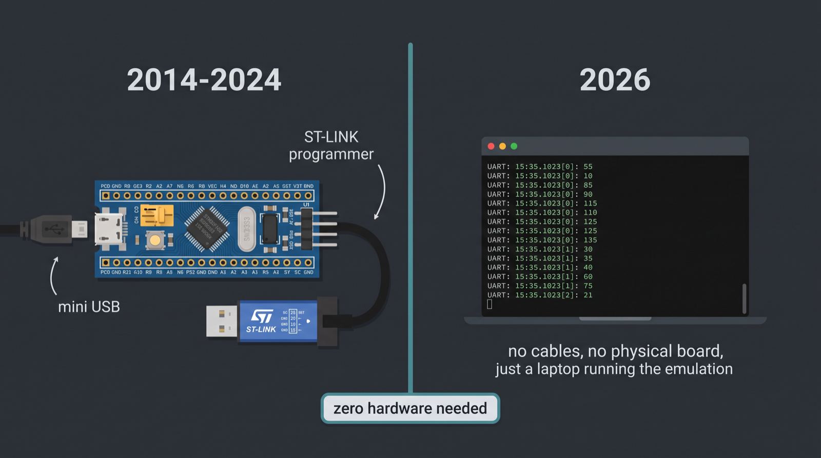
Running the Blue Pill on Chiplab
Chiplab has a board model for it: stm32f103_blue_pill. Hand it an ELF, get back a run id and a
UART transcript — same interface as every other board we support, no board-specific setup on
your end. Under the hood, this runs on Renode, the same MIT-licensed simulator behind the rest
of our board fleet. I've written before about why we point people at Renode instead of trying
to build our own core from scratch, and the short version holds
here too: reimplementing peripheral models for every MCU family on the market is not a fight
worth picking when a maintained open-source one already exists and covers most of the ground.
What that buys you in practice: an STM32F103 Blue Pill simulation that isn't a stub faking a UART print and calling it a day. It's a real CPU core executing real machine code against a model of real peripheral registers, clock tree included. Whether that model is complete for every peripheral is a separate question — and it's the one the rest of this post is actually about.
The firmware
Bare-metal Rust, no RTOS, using stm32f1xx-hal — the crate anyone writing Rust for this chip
family reaches for. It brings up PC13 as a push-pull output (PC13 drives the Blue Pill's onboard
LED, on the opposite rail from most boards' active-low convention, which trips up everyone the
first time they blink it), configures USART1 on PA9/PA10 at 115200 baud, prints a banner, and
toggles the LED six times while narrating each toggle over UART:
#![no_main]
#![no_std]

use cortex_m_rt::entry;
use panic_halt as _;
use stm32f1xx_hal::{pac, prelude::*, serial::Config};

#[entry]
fn main() -> ! {
    let dp = pac::Peripherals::take().unwrap();
    let mut rcc = dp.RCC.constrain();

    let mut gpioc = dp.GPIOC.split(&mut rcc);
    let mut led = gpioc.pc13.into_push_pull_output(&mut gpioc.crh);

    let mut gpioa = dp.GPIOA.split(&mut rcc);
    let tx = gpioa.pa9.into_alternate_push_pull(&mut gpioa.crh);
    let rx = gpioa.pa10;

    let mut serial = dp.USART1.serial(
        (tx, rx),
        Config::default().baudrate(115_200.bps()),
        &mut rcc,
    );
    // ... prints a banner, toggles PC13 six times, prints each toggle over UART ...
}
There's nothing exotic in here on purpose. This is the shape every Blue Pill tutorial from the last five years converges on: constrain RCC, split a GPIO port, configure a pin, bring up a UART. Which is exactly why it's the right firmware to run first. If the simulation has an opinion about this code, it has an opinion about a large fraction of everything actually written for this chip.
Running it today, unedited
Board id stm32f103_blue_pill, minted today. Here's the
stdout, verbatim:
08:07:06.4193 [WARNING] sysbus: [cpu: 0x8000406] WriteDoubleWord to non existing peripheral at 0x42420310, value 0x1.
08:07:06.4195 [WARNING] sysbus: [cpu: 0x800040E] WriteDoubleWord to non existing peripheral at 0x42420190, value 0x1.
08:07:06.4219 [WARNING] gpioPortC: Trying to set the state of the input pin #13
08:07:06.4365 [INFO] usart1: [host: 0.18s (+0.18s)|virt: 0s (+0s)] bluepill-hello: $2 board, zero hardware, still boots
08:07:06.4369 [INFO] usart1: [host: 0.18s (+0.58ms)|virt: 0s (+0s)] toggle 0 -> PC13 on
08:07:06.4372 [INFO] usart1: [host: 0.18s (+0.26ms)|virt: 0s (+0s)] toggle 1 -> PC13 off
08:07:06.4415 [INFO] usart1: [host: 0.18s (+0.25ms)|virt: 0s (+0s)] toggle 5 -> PC13 off
08:07:06.4422 [INFO] usart1: [host: 0.18s (+0.63ms)|virt: 0s (+0s)] done, 6 toggles observed over UART on the classic Blue Pill
It boots. The banner prints. All six toggles get logged over UART, in order, and the run reports done by its own bookkeeping. If this were the only thing I read, I'd call it a clean pass and move on to the next board.
But there are two warnings sitting above the first UART line, and a third right after them, and they're worth reading instead of scrolling past on the way to the green-looking part.
The honest finding
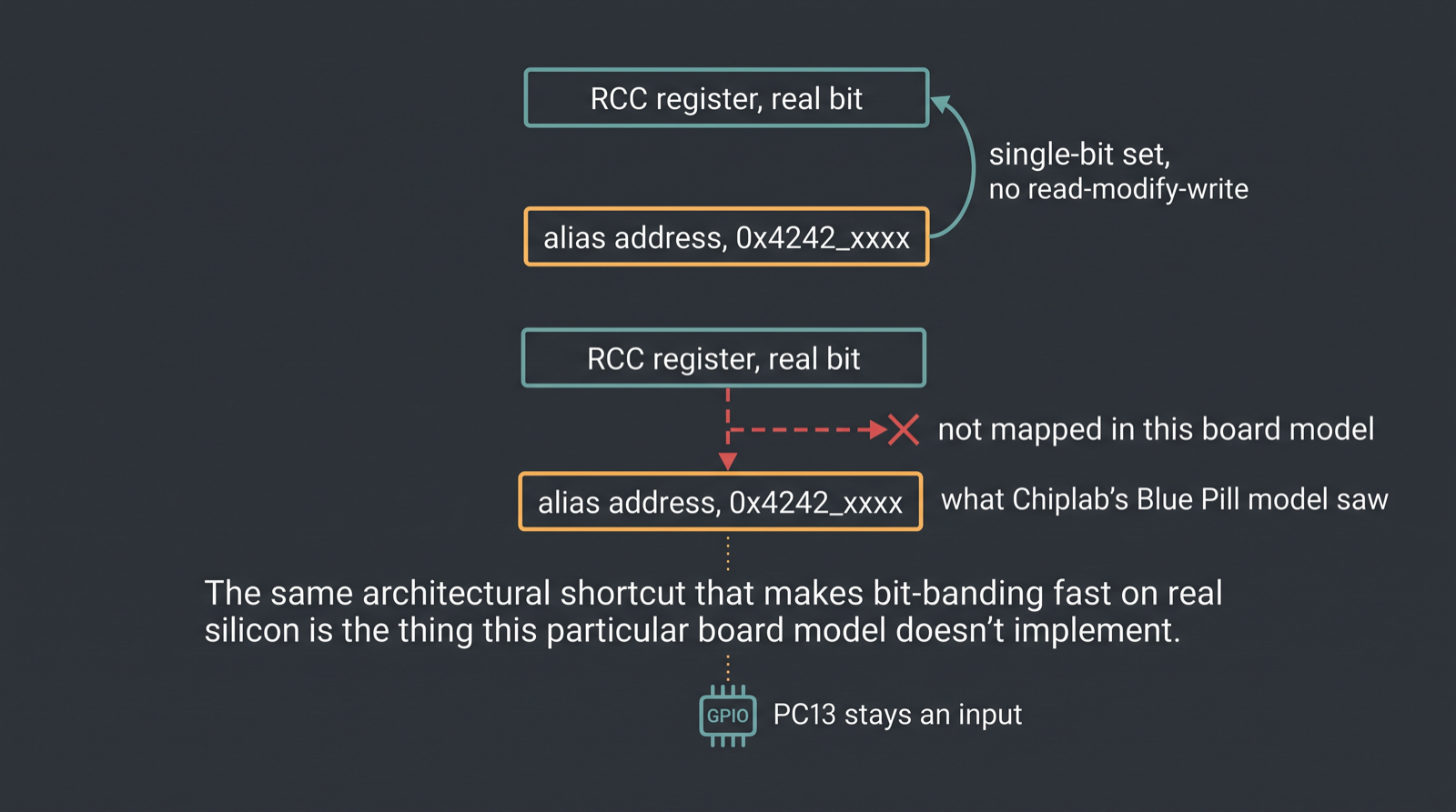
Both early warnings share a shape: WriteDoubleWord to non existing peripheral at addresses
0x42420310 and 0x42420190. Those addresses aren't garbage — they sit in the
0x4200_0000–0x43FF_FFFF range, which on a real Cortex-M3 is the peripheral bit-band alias.
Writing a word to an address in that range doesn't write "a word" at all. The hardware decodes
it into a single-bit set or clear on the actual peripheral register the alias maps to,
atomically, with no read-modify-write required. That's a real ARM architecture feature, not
something Renode invented to be difficult.
stm32f1xx-hal uses exactly this mechanism, and it's right there in the crate's own source. A
small bit-banding helper (src/bb.rs) is what the crate reaches for specifically to flip
individual clock-enable and reset bits in the RCC peripheral, before it goes on to configure
GPIOC, GPIOA, and USART1 — which is precisely the sequence this firmware runs on the way to
bringing up the LED pin and the UART. Chiplab's Blue Pill board model doesn't implement that
alias address range. The writes land on addresses nothing is mapped to, and Renode logs it
honestly instead of quietly pretending the write succeeded.
The next line is where it gets interesting: gpioPortC: Trying to set the state of the input pin #13. That's Renode's own GPIO port model, a separate subsystem from the sysbus warnings above
it, complaining that the firmware is calling something like set_high() or set_low() on PC13
while the port still considers that pin an input — even though the code explicitly calls
into_push_pull_output a few lines earlier in the same function.
I didn't get to read Renode's internal GPIO model source for this post, so I'll stick to what I can actually support: these two symptoms are likely connected, not confirmed connected. The RCC bit-band writes that vanished are the same writes that should be enabling the clock domain this pin's configuration depends on, and a GPIO port that never saw that clock enable land would explain a port that still thinks pin 13 is an input. That's an inference built from two real log lines, not a root cause traced step by step through Renode's own peripheral model — and it's worth being precise about which of those two things this actually is.
What I can say without any hedging at all: UART worked perfectly, start to finish. USART1's configuration path in this HAL doesn't route through the same bit-band shortcut for the bits that matter here, so it's unaffected by whatever's happening to PC13. The banner printed, all six toggle lines printed in order with the delta timestamps ticking along normally, and the run reported done. If your firmware's job today is "talk over UART," this board model has your back. If your firmware's job is "blink an LED and prove it happened," you'd want to know about this before you trust the green-looking output.
This is exactly the kind of thing I keep finding across this batch of posts: simulators are honest about what they don't model, provided you actually read the log instead of scanning for the word "error" and stopping there. Nothing in this transcript says FAIL. Both problem lines say WARNING and "Trying to," which is Renode telling you plainly that it doesn't know what to do with an address and is doing something reasonable — log it and move on — instead of crashing or, worse, silently succeeding.
Compare that to the F4
I ran the STM32F4 Discovery through the same kind of exercise — FreeRTOS, USART2, no hardware — and that transcript had zero warnings. Not "warnings I chose to leave out of the post." Zero, top to bottom. The Blue Pill is not Chiplab's best-supported board, and I'm not going to pretend otherwise just because it's the one with the nostalgia angle this week. The F4 Discovery is the newer, more heavily exercised part in our own examples, and its Cortex-M4 board model has had more attention put into it than the F103's Cortex-M3 model has.
The gap between those two runs is the honest state of things right now: less-travelled boards surface more corner cases, and the STM32F103 Blue Pill simulation, while genuinely useful today, is one of the boards where that shows up in the log if you go looking. That's not a knock on the platform. It's the platform working as intended — telling you where the coverage is thinner instead of hiding it behind a passing exit code.
One sentence on Embassy, and no more than one: Chiplab also supports an Embassy-async firmware target for this board. I didn't run that variant today. Everything above is the bare-metal run, and I'm not going to describe output for a firmware image I don't have a transcript for.
What actually happened here
A ten-year-old clone board, running firmware built with a HAL crate that was never written with
Chiplab in mind, hit a real Cortex-M3 architecture feature that this particular board model
doesn't implement — and the simulator told me about it in plain English instead of lying about
it. That's not a knock against bit-banding, which is doing exactly what it's supposed to do on
real silicon. It's not a knock against stm32f1xx-hal either, which is using a real chip feature
the way it's meant to be used. It's a gap in one board model's peripheral coverage, logged
instead of hidden, on a $2 board you no longer need to own to go find it on.
The LED bug is real and worth fixing on our end. The UART transcript is real and worth trusting today. Both of those things are true at once, and the log is the only reason I know which parts are which.